Simulating the Skeleton of a Processor Core
Simulating the Skeleton of a Processor Core
This is the first post in our multi series blog describing the process of designing a RISC-V processor core using a hardware definition language, namely SystemVerilog. In this post we are not going to go much into the process of designing the processor core itself. Rather, this post will focus on the getting started part, which we need to accomplish before implement the actual processor design.
The first step in creating our own processor core is to create the testbench, the models and to set up the simulation environment. To simulate our processor core, we need to instantiate it at a top level from where we can apply different stimulus (or inputs) to the core and monitor the outputs to verify the correctness of our design.
Moreover, we do not need to “design” the the memory our processor core is going to be using. The actual memory in real life would probably be a separate chip, a different IP on the same chip or SoC, or maybe even an embedded block if using an FPGA. It would however, not be practical to design an actual memory using a hardware definition language like SystemVerilog. Nevertheless, to simulate our processor core, we would need to have something to use as a memory block. For the purposes of this tutorial, we are going to write some very basic memory models and then we will use that model to verify the correctness of our processor core.
Creating the Memory Model
For the memory, we are going to create a model with dual read/write ports. These two ports will be able to read from or write to the same memory space simultaneously. One of these would be used as the instruction memory and the other one would be for data memory. We can save the memory model in vsim/models/dual_port_memory.sv file. This model is going to have enable, write enable, data in and address as inputs for each of the two memory ports. The outputs would be busy signal and the data out bus for each of the two ports. The model needs to have an address space declared as an array. The input output ports we are going to be using as as follows:
| Name | Type | Description |
|---|---|---|
| rst_n_i | I | Asynchronous active low reset |
| clk_i | I | Clock |
| en[1|2]_i | I | Enable signal for memory port [1|2] |
| wen[1|2]_i | I | Write enable signal for memory port [1|2] |
| addr[1|2]_i | I | Address bus for memory port [1|2] |
| data[1|2]_in_i | I | Data in bus for memory port [1|2] |
| data[1|2]_busy_o | O | Memory port [1|2] busy indicator |
| data[1|2]_out_o | O | Data out bus for memory port [1|2] |
We will use a parameter MEMSIZE to identify the size of the memory in bytes. We will make the default value of this parameter 'h10000 which is 64kB of memory. Our memory model is going to be very simple and will be able to read/write 4 bytes at a time and only accept 4byte aligned memory addresses. To easily support this, we can just divide the memory size in bytes by 4 and use that number as the size of the memory space array where each element will be a 32 bit logic element. We will name this array data and declare it the following way.
  parameter int MEMSIZE = 'h10000;  // Has to be multiple of 4
  localparam int MEMSIZE_BY_4 = MEMSIZE / 4;

  logic [31:0] data[MEMSIZE_BY_4-1:0];  // MEMSIZE bytes
We need to know the address space offset where the generated machine code is going to reside. The programs we will generate will have the text section starting at a non zero address. And to make the simulation use less memory, we are only going to model the address starting form this address + 64kB. We will keep the text section offset into a parameter called TEXT_OFFSET and the offset for the data section into DATA_OFFSET. For now we can keep whatever default values in them and later when instantiating the memory model we can give the proper parameter values.
Outputting the data out will happen only when the enable signal is hi and the write signal is lo. In this simple model we are going to output the data instantly instead of waiting for the next clock cycle. However, we will use the internal busy signal to mask the data out. Later we will be able to use random or fixed pattern of the busy signal to verify that our processor core is able to stall properly when the memory is busy. The actual data out code would be very simple combinational logic and would look like this:
  always_comb begin
    data1_out_o = '0;

    if (wen1_i == 1'b0 &&
        en1_i == 1'b1 &&
        data1_busy_o == 1'b0) begin

      data1_out_o = data[(addr1_i - TEXT_OFFSET)/4];
    end
  end
Note that we would need something similar for the other memory port as well.
To implement the memory write logic into out model we are going to need to use the clock. The writing will happen only on the positive edge of the input clock and when both the applicable enable and write enable signals are hi. It could look something like this:
  always_ff @ (posedge clk_i) begin
    if (wen1_i == 1'b1) begin
      data[(addr1_i - TEXT_OFFSET) / 4] <= data1_in_i;
    end
  end
Again, we would need to implement something similar for the other memory port as well.
Finally, we need a way to load the memory content from input hex file at the beginning of simulation. For this we can make use of the Verilog $readmemh command. This takes the hex file name as the first argument and the memory array as the second argument. Note, that this hex file is not the intel hex file. This file is a just ascii hex values. Moreover, we want a way to provide the name of the hexfile as argument when running the simulator. This way we would not have ot re-compile the verilated C++ code for running different hexfiles and we can do quick regression of all of our assembled code quickly. For this we can use the Verilog command $value$plusargs, which takes a pattern as the first argument and the string variable to store the result into as the second argument (I personally don’t like passing argument as reference and then modifying them, but we are stuck with Verilog…). Our initial block inside the dual_port_mem module would look like this:
  initial begin
    if (HEXFILE_FROM_ARG) begin
      if ($value$plusargs("text_hexfile=%s", memfile)) begin
        $display("INFO: loading %s", memfile);
        $readmemh(memfile, data);
      end else
        $display("ERROR opening hexfile");
      if ($value$plusargs("data_hexfile=%s", memfile)) begin
        $display("INFO: loading %s", memfile);
        $readmemh(memfile, data, (DATA_OFFSET - TEXT_OFFSET) / 4);
      end else
        $display("ERROR opening hexfile");
    end else begin
      $readmemh(MEMFILE, data);
    end
  end
Here memfile is a string and MEMFILE is a string parameter that is set to a hexfile with all zeros as default. HEXFILE_FROM_ARG is an int parameter that defaults to 0, but can be set as 1 from the instantiating module. This way from the top level we can provide either an explicit memory file or set HEXFIRL_FROM_ARG to 1 to make the module load the memory file based on the simulator argument. The final memory model we are going to be using can be found here.
Creating the Testbench Top and the Processor Core Skeleton
Next we are going to create the basic module file for our processor core. We will keep this file in src/core.sv. For now this is going to be just an empty shell with the inputs and outputs defined. It is going to look like this:
module core(
  rst_n_i,
  clk_i,

  dm_dout_i,
  dm_wen_o,
  dm_en_o,
  dm_din_o,
  dm_addr_o,
  dm_busy_i,

  im_dout_i,
  im_addr_o,
  im_busy_i
);

  input logic rst_n_i;
  input logic clk_i;

  input logic [31:0] dm_dout_i;
  output logic dm_wen_o;
  output logic dm_en_o;
  output logic [31:0] dm_din_o;
  output logic [31:0] dm_addr_o;
  input logic dm_busy_i;

  input logic [31:0] im_dout_i;
  output logic [31:0] im_addr_o;
  input logic im_busy_i;

endmodule
Our simulation top module is going to be very simple as well. We are going to give this module a creative name, “top”. This module will just instantiate the dual_port_mem and the core modules. We are going to declare some local signals and use them to connect the core and the dual port memory with proper corresponding signals. We are going to use the memory port 1 as the interface used by data memory and the memory port 2 as the instruction memory. Hence these signals are connected in this way in top.sv. Notice that we need to provide the values for the parameters HEXFILE_FROM_ARG, TEXT_OFFSET, and DATA_OFFSET. We want the memory model to use the simulator argument to load the initial memory values from. Furthermore, we want the text offset to be 32’h80000000, and the data offset to be 32’h80002000. These values are used by the rocket chip and would be easier to compile code using rocket chip’s link.ld. There is no reason these offset values can’t be something different. This module is going to have the reset and the clock signals as input, which will be driven from the verilator program. For communication with the outside world, we are going to create a very basic model of this functionality. Out “tohost” address is going to be 32’h80001000. To model data being sent to the host using a top level port, we are going to have the output signals tohost_int_o, and tohost_data_o. The idea being, whenever there is data on this port for the host, the int signal is going to be raised and the host needs to read it instantly. This simple logic can be modeled using these two lines of combinational code:
  assign tohost_int_o = (dm_wen && dm_addr == 32'h80001000);
  assign tohost_data_o = tohost_int_o == 1'b1 ? dm_din : '0;
We are going to keep this file in vsim/tb/top.sv location. And the entire file should look like this:
module top(
  rst_n,
  clk,
  tohost_int_o,
  tohost_data_o
);

  input logic rst_n, clk;

  output logic [31:0] tohost_data_o;
  output logic tohost_int_o;

  logic [31:0] dm_dout;
  logic dm_wen;
  logic [31:0] dm_din;
  logic [31:0] dm_addr;
  logic dm_busy;

  logic [31:0] im_dout;
  logic [31:0] im_addr;
  logic im_busy;

  core u_core(
    .clk_i          (clk),
    .rst_n_i        (rst_n),

    .dm_dout_i      (dm_dout),
    .dm_en_o        (dm_en),
    .dm_wen_o       (dm_wen),
    .dm_din_o       (dm_din),
    .dm_addr_o      (dm_addr),
    .dm_busy_i      (dm_busy),

    .im_dout_i      (im_dout),
    .im_addr_o      (im_addr),
    .im_busy_i      (im_busy)
  );

  dual_port_mem #(
    .HEXFILE_FROM_ARG(1),
    .TEXT_OFFSET(32'h80000000),
    .DATA_OFFSET(32'h80002000)
  ) u_mem (
    .rst_n_i        (rst_n),
    .clk_i          (clk),
    .en1_i          (dm_en),
    .wen1_i         (dm_wen),
    .addr1_i        (dm_addr),
    .data1_in_i     (dm_din),
    .data1_out_o    (dm_dout),
    .data1_busy_o   (dm_busy),
    .en2_i          (1'b1),
    .wen2_i         (1'b0),
    .addr2_i        (im_addr),
    .data2_in_i     (32'h0000),
    .data2_out_o    (im_dout),
    .data2_busy_o   (im_busy)
  );

  assign tohost_int_o = (dm_wen && dm_addr == 32'h80001000);
  assign tohost_data_o = tohost_int_o == 1'b1 ? dm_din : '0;

endmodule
Running the Simulation and Viewing Signals
To run the simulation, we will need a top level c++ program that instantiates the top level SystemVerilog module and provides proper inputs and checks the expected outputs. We could have skipped a step and just instantiated the memory and the core in this program. But this way we get to keep the top.sv unchanged and use it as the top level for any other non-verilator simulator what we may use later. I have created a cpp file by making slight modification to the sim_main.cpp file given as an example. We will save the modified cpp file in vsim/sim_main.cpp. There is a lot going on in this file. The changes that we are going to make in this file includes adding the ability to run the program with an extra argument to set the logfile name. This will help us run multiple RISCV programs as regression tests. The other major change is inside the main function itself:
    // Set some inputs
    top->rst_n = 0;
    top->eval();
    top->clk = 0;
    top->eval();
    top->clk = 1;
    top->eval();
    top->rst_n = 1;
    top->eval();

    int test_done = 0;

    // Simulate until $finish
    while (!Verilated::gotFinish() && main_time < 6000) {
        main_time++;
        top->clk ^= 1;

        if (main_time % 2 == 1) {
            if (top->tohost_int_o == 1) {
                std::string test_status;
                if (top->tohost_data_o == 1) {
                    test_status = "PASS";
                } else {
                    test_status = "FAIL";
                }
                printf("TEST %sED\n", test_status.c_str());
                std::ofstream f;
                f.open(logout.c_str(), std::ios::out);
                f << test_status << std::endl;
                f.close();
                test_done = 1;
                break;
            }
        }


        top->eval();
#if VM_TRACE
        tfp->dump(main_time);
#endif
    }

    // Do a couple of clock cycles for easier waveform debugging
    main_time++;
    top->clk ^= 1;
    top->eval();
#if VM_TRACE
        tfp->dump(main_time);
#endif
    main_time++;
    top->clk ^= 1;
    top->eval();
#if VM_TRACE
        tfp->dump(main_time);
#endif


    if (test_done == 0) {
        printf("TEST TIMEOUT");
    }
Here we first apply the reset (active lo, rst_n_i = 0 means the parts are in reset), apply a few clock cycles and call the verilator eval function a few times in between. Without calling the eval function, verilator does not apply the inputs to the design. and needs to be called every time an input is changed. In our case we will change the inputs, change the clock and then call the eval function for every clock cycle after reset.
In the while block, we loop until either the $finish function is called from somewhere in Verilog or the main time counter variable has reached a timeout value (6000 in this case). We invert the clock input of top on every iteration of the while loop. We also check whether any data is sent from the processor by polling the the tohost_int signal. We will later use programs that will return 1 in case the test has passed, and hence this kind of check will become very useful. Finally after the loop we apply the clock one ore time to make sure we have some extra data after the test finish condition is over. This ensures that we have enough data after the test finish condition for easier debugging. The final sim_main.cpp file can be found here.
Next step before running the simulation is to create a Makefile for the make tool that we will be using. We will keep this Makefile in the vsim/ directory as well. Similar to the cpp file, we are going to use the verilator example Makefile as a starting point as well. The changes we will make to the Makefile includes adding the -Wno-fatal flag, adding our src directory as include. Since we are keeping the models and the tb directory within the vsim directory, there is no need to explicitly add these to the input. Finally we will copy the Makefile_obj and the input.vc files from the Verilator example directory. We have added a couple of variables, namely HEX and HEX2 to the Makefile. These both point to hex/zeros.hex where the zeros.hex is a all zero hexfile. When we run make, we can explicitly set these hexfiles to something else, otherwise the all zeros file will be used by default.
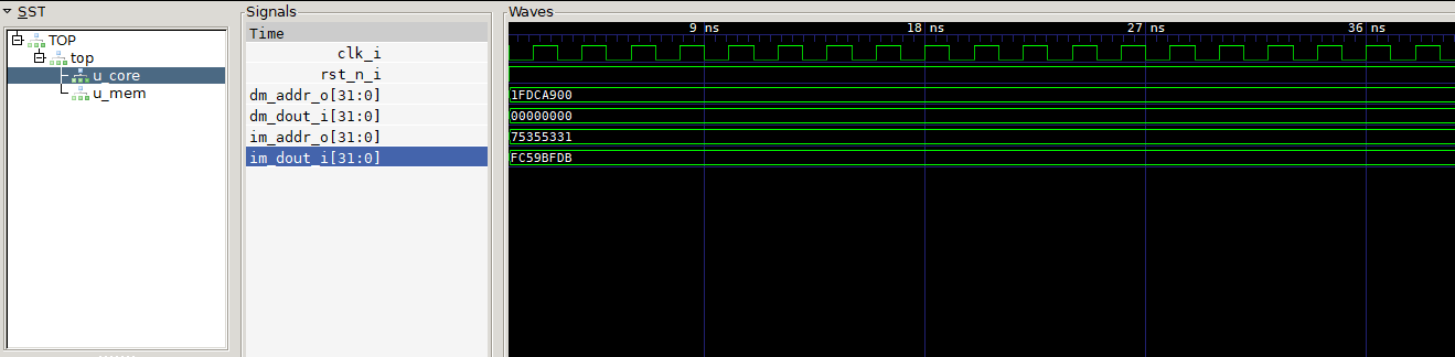
To run the simulation then we need to run make from the vsim directory. This should create a obj_dir directory with various cpp files in them. Next it will compile these cpp files and use the compiled code to run the simulation. This step should also create a vcd file in the logs directory in the process. To open the vcd file we will need to use a vcd file view. One of the most popular open source vcd file viewer is gtkwave. You can use gtkwave to open the vcd file and look at the signal. Right now our processor core is not going to do anything. All we will be able to see is the reset changing from zero to 1 and the clock signal toggling. We can also plot the instruction memory out and data memory out signals. We expect these values to be zero as well since the memory is loaded from zeros.hex. However, if these are not zero, don’t worry about it. As long as the reset and clock signals behave as expected, it should be ok to go forward with the next steps. In the next blog post we are going to actually start designing the core and we will see more signals toggling.
You can find all the steps described in this post here